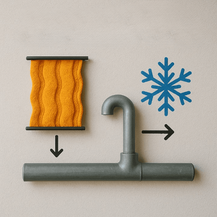
The majority of substances tend to increase in volume with heat and decrease in volume when exposed to lower temperatures. This behaviour, known as thermal expansion, is something engineers have learned to accommodate—or sometimes even exploit. But what if we wanted the opposite? What if a material or system contracts when heated and expands when cooled?
Welcome to the world of Reverse Thermal Expansion Systems (RTES). While it may sound like science fiction, materials and systems that behave this way are very real and increasingly important in applications requiring dimensional stability under temperature fluctuation. In this blog, we’ll walk through the key principles behind designing a Reverse Thermal Expansion System—focusing on the science, material selection, and engineering challenges.
1. Understanding the Phenomenon: What Is Reverse Thermal Expansion?
Under typical conditions, standard materials exhibit expansion upon heating and contraction when cooled. This behaviour is quantified by the Coefficient of Thermal Expansion (CTE)—usually a positive value.
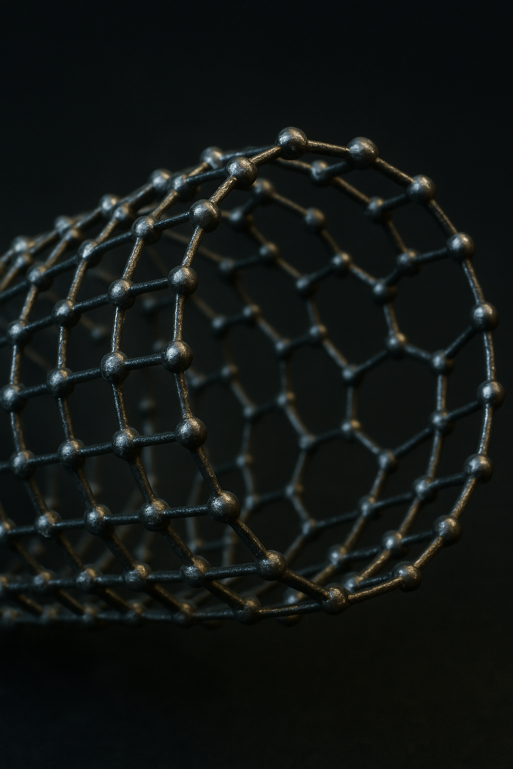
Reverse thermal expansion occurs when a material possesses a negative thermal expansion coefficient, leading it to contract when heated and expand as it cools. This counterintuitive behaviour arises from unique atomic, molecular, or structural interactions, such as:
- Rigid Unit Modes (RUMs): Where atomic polyhedra rotate instead of stretching.
- Lattice distortions: Triggered by temperature shifts without volume increase.
- Geometric frustration: Which causes structural collapse on heating.
Understanding this mechanism is vital because it helps determine whether a negative CTE is intrinsic to the material or must be engineered through structural design.
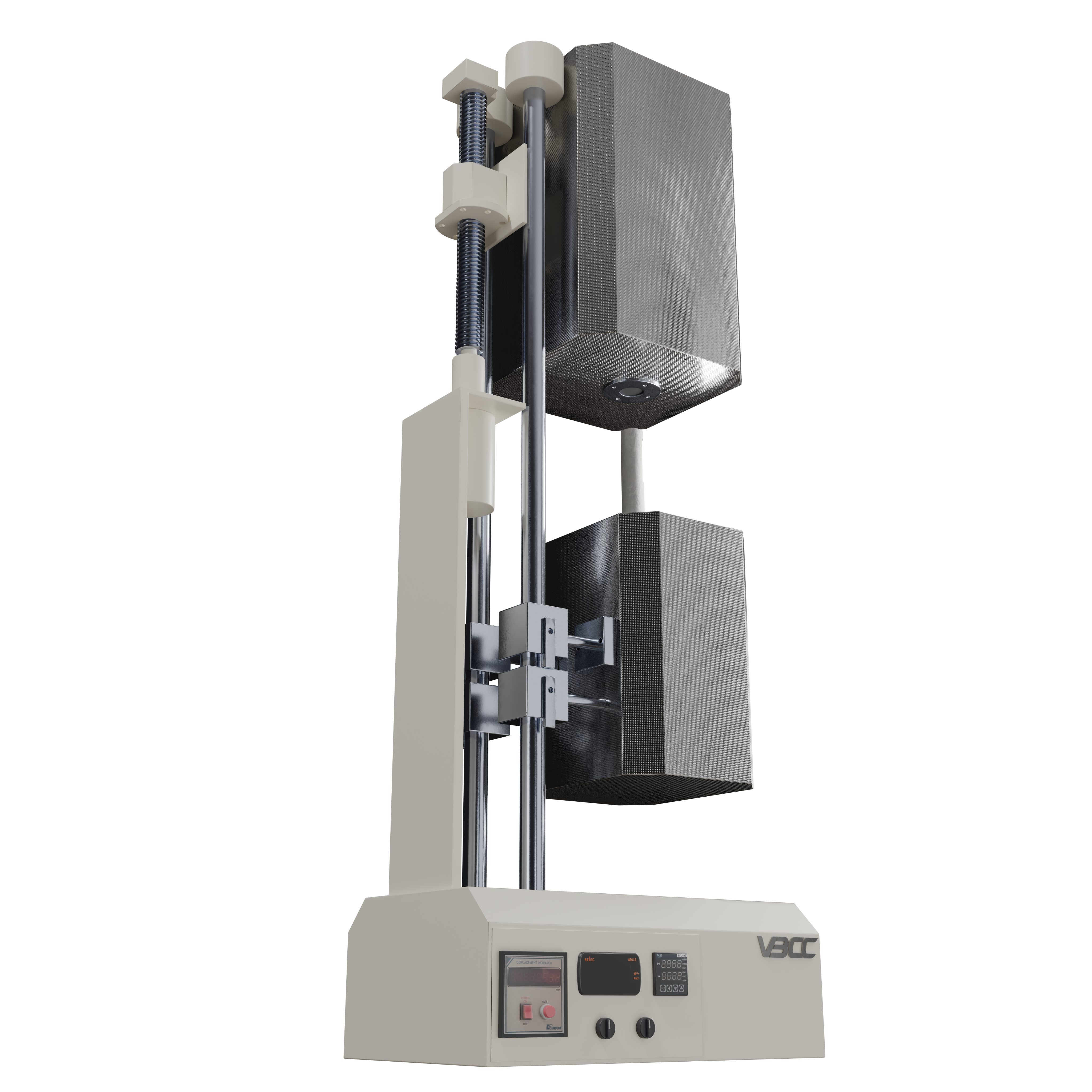
2. Select or Engineer the Right Materials
The material is the heart of any RTES. You have three main pathways:
A. Intrinsically NTE Materials
Certain materials inherently display negative thermal expansion within defined temperature ranges:
- Zirconium Tungstate (ZrW₂O₈): Demonstrates thermal contraction consistently from 0.3 K up to 1050 K.
- Scandium Trifluoride (ScF₃): Exhibits uniform contraction across all axes at high temperatures.
- Perovskite-structured oxides: Tunable for CTE via doping.
Pros: No need for complex structures.
Cons: Limited temperature range, potential brittleness.
B. Composite Materials
By layering or mixing materials with contrasting CTEs, you can create composite structures with engineered average expansion behaviour. For instance:
- Fiber-reinforced polymers
- Metal-ceramic laminates
- Carbon nanotube composites
Key Design Metric: The rule of mixtures and mismatch strain calculations help predict effective behaviour.
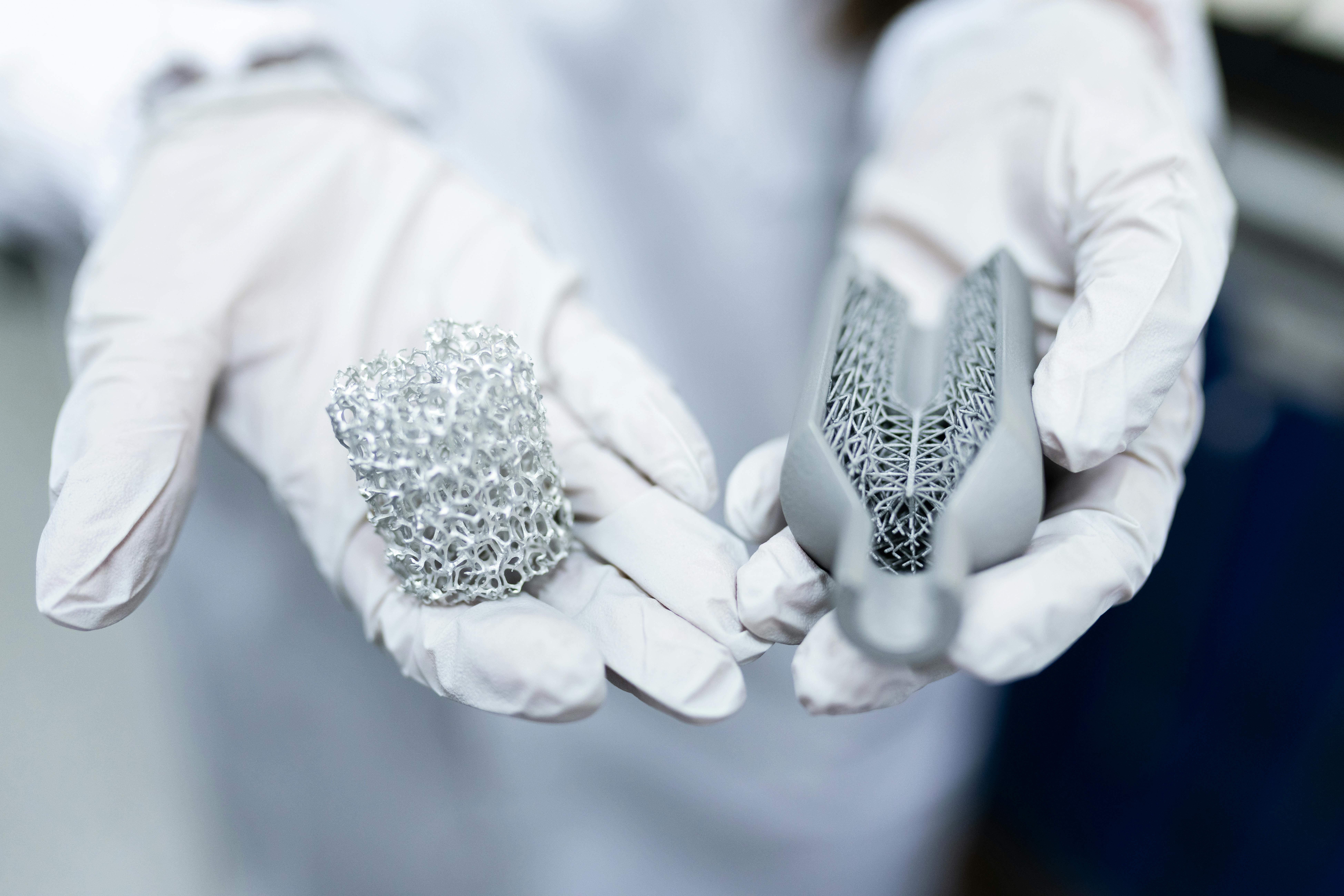
C. Architected Metamaterials
3D-printed or micro-machined can be programmed to exhibit reverse expansion based on unit cell design, regardless of base material.
Example: A truss-like micro-lattice made of aluminium can be designed to shrink overall even as the metal expands locally.
3. Utilize Geometry to Amplify or Tune Behaviour
Geometry plays a crucial role, especially when working with composite or metamaterial-based RTES. Key approaches include:
A. Bimetallic Actuation
When two metals with different coefficients of thermal expansion (CTEs) are joined in a strip, they can bend in response to temperature changes, as seen in thermostats. Reverse behaviour can be designed by:
- Adjusting thickness ratios
- Pre-stressing the assembly
- Controlling interface bonding
B. Auxetic & Lattice Structures
- Auxetic structures (with negative Poisson’s ratio) can deform in ways that lead to overall contraction.
- Origami-based designs can enable large, reversible motion under small thermal loads.
C. Topology Optimization
Advanced algorithms allow you to design internal geometry that manipulates thermal flow and deformation paths to achieve reverse expansion characteristics.
4. Model Thermomechanical Behaviour Early
Thermal performance is not intuitive at system level—you must simulate it. This reduces trial-and-error and ensures reliability.
Tools & Methods:
- Finite Element Analysis (FEA): Model deformation, stress, and strain due to temperature changes.
- COMSOL Multiphysics / ANSYS / Abaqus: For coupled thermal-mechanical modelling.
- Sensitivity Analysis: Identify critical parameters like temperature thresholds or stress limits.
What to Simulate:
- Thermal cycling and fatigue
- Heat distribution under operating conditions
- Structural response to constrained expansion/contraction
Pro Tip: Simulate interfaces and joints carefully—they're often the failure points under thermal cycling.
5. Design for Manufacturability and Reliability
Having a great model is only half the battle. You must build and scale it—so your RTES must be manufacturable and durable in the real world.
Manufacturing Techniques:
- Additive manufacturing(3D printing): Enables complex geometries and micro-lattice structures.
- Laser sintering and micromachining are effective techniques for producing high-precision parts.
- Composite layup or lamination: For large-scale or layered systems.
Material Compatibility:
- Adhesives and joints: Must survive repeated temperature cycles.
- Creep resistance: Materials should not deform permanently under heat over time.
- Corrosion resistance: Important in high-humidity or chemically aggressive environments.
Pro Tip: Use accelerated thermal cycling tests to estimate a product's durability over time
6. Control & Feedback Mechanisms
Some RTES are passive, but others can benefit from smart, responsive control systems. Consider integrating:
A. Temperature Sensors
- Thermistors or RTDs to measure real-time temperature.
- Allows dynamic feedback for control systems (e.g., actuators or dampers).
B. Embedded Microcontrollers
- Run feedback loops or adjust system constraints based on readings.
- Useful in robotics, aerospace, or HVAC.
C. Smart Materials Integration
- Materials like Shape Memory Alloys (SMA) or Phase Change Materials (PCM) can respond dynamically to heat and work in tandem with RTES to amplify motion or control thermal damping.
D. Fail-Safes and Limits
- Add mechanical stops or redundancy for critical applications (e.g., aircraft, medical devices).
Applications That Drive the Need
Reverse thermal expansion systems are already finding their way into:
- Aerospace components that must maintain tight tolerances in orbit
- Precision instruments like telescopes and microscopes
- Energy systems, including heat exchangers and battery enclosures
- Advanced infrastructure systems that can adjust to thermal loading variations

Designing a Reverse Thermal Expansion System isn’t about flipping a switch—it’s about leveraging physics, material science, and structural engineering to create thermally adaptive systems. While still a growing field, the potential applications are vast and high-impact. By combining innovative materials, smart design principles, and robust modelling, engineers can build systems that don't just withstand temperature changes—but thrive on them.
